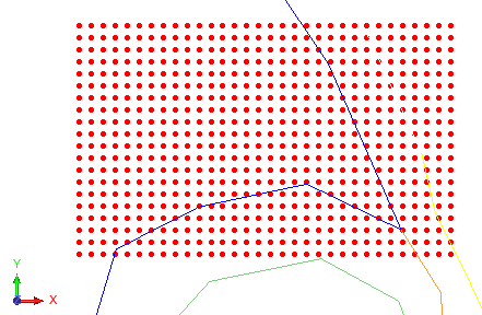
Blast rectangle
You can use this command to create a grid that represents a drillhole blast pattern.
Prerequisites: Graphics is set to plan view. If you want to use the rock name to modify the burden and spacing, a string must be displayed with the rock name stored in the D field of each point.
To run this function: Choose Design > Blast Design > Blast Design > Create blast pattern, or...
You are prompted to drag in Graphics to select the area where the blast holes will appear, and to press F2 to create the holes. You can also drag with the left mouse button to move the area, or CTRL+drag with the left mouse button to rotate the area.
Fields on the Blast pattern design form
Pattern settings tab
| Field | Description |
|---|---|
| Blasting grid | |
| X | The X position of the lower left corner of the grid design box. |
| Y | The Y position of the lower left corner of the grid design box. |
| Grid height | The length (burden) of the grid design box. |
| Grid width | The width (spacing) of the grid design box. |
| Grid angle | The bearing of the Y direction (burden direction) of the grid design box. That is, the amount by which the grid pattern is rotated from North in plan view. |
| Blast settings | |
| Pattern identifier | The name of the hole pattern. |
| Drill rig | The name of the drill rig. |
| Blasting method | A description of the blasting method for the defined hole pattern. This text is stored in the drill and blast database if you upload the blast holes to the database. |
| Ground water level | The level of ground water. This text is stored in the drill and blast database if you upload the blast holes to the database. |
| Burden and spacing | |
| Modify burden and spacing by polygon |
|
| Manual burden/spacing | |
| Rock name |
The rock mass classification that you want to give to the blast holes. This will be the value of the RMC property for the blast holes you create.
|
| Spacing method |
|
| Burden | The distance between rows of blast holes. This box is visible only when Spacing method is Burden and spacing. |
| Spacing | The distance between blast holes in the same row. This box is visible only when Spacing method is Burden and spacing. |
| No. rows | The number of rows of blast holes. The first row is created on the lower line of the design box. This box is visible only when Spacing method is Number of holes. |
| No. columns | The number of columns of blast holes. The first column is created on the left side of the design box. This box is visible only when Spacing method is Number of holes. |
| Clip to boundary |
|
| Burden/spacing by polygon | |
| Rock classification attribute | The D field that holds rock type, in the polygons that mark the boundary of each rock zone. |
| [Rock type table] | This table displays the burden, spacing, and subdrill for each rock type in the drill and blast settings. If you edit burden, spacing, or subdrill for any rock type in this table, and blast holes are created on that rock type, the new burden, spacing, or subdrill is used. |
| Blast layout |
|
| Hole order |
|
 Note: In


Hole settings tab
| Field | Description |
|---|---|
| Collar elevation | |
| Elevation method |
|
| Elevation | The elevation value of all drillholes. |
| Make Visible? |
This option is visible only when Elevation method is set to DTM file. |
| Toe elevation | |
| Toe position method |
Toe position method is the method Surpac uses to determine the length of each blast hole.
|
| Hole length | The length of all blast holes. |
| Subdrill distance | The extra drilling length to add to each hole (when Modify burden and spacing by polygon is cleared). |
| Hole settings | |
| Hole bearing | The bearing (also known as azimuth) of all holes in the pattern. For vertical holes, you can set hole bearing to any value. Zero is typically used for the bearing of vertical holes. The bearing is measured as the azimuth in plan view from the collar to the toe, or end of the hole. |
| Hole dip | The dip of all holes in the pattern. For vertical holes drilled down, hole dip should be set to -90. For horizontal holes, the dip should be set to zero. The dip is measured as the angle from the horizontal plane to the toe, or end of the hole. |
| Hole diameter | The hole diameter in units of measure. If the metric system is used, the value is in metres. For example, you would enter a 76mm hole as 0.076 (metres). If the imperial system is used, the value is in feet. For example, a 6 inch hole would be entered as 0.5 (feet). The diameter is written to the D4 field of the first point of the segment which represents the hole. |
| Labelling options | |
| Hole ID prefix | The numeric hole name. For example, to number the
holes 940-1, 940-2, 940-3, and so on, you would enter 940- as
the hole ID prefix. You can leave the hole ID prefix blank. If
it is blank, the holes are numbered 1, 2, 3, and so on. |
| Include rock class? | Select Modify burden and spacing by polygon to enable this option.
|
| Hole ID suffix | The numeric hole name. For example, to number the
holes 1rc, 2rc, 3rc and so on., you would enter rc as the hole
ID prefix. You can leave the hole ID suffix blank. If it is
blank, the holes are numbered 1, 2, 3, and so on. |
| Starting value | The starting number for the incremental part of the hole ID. |
| Sequence rows |
|
| Row increment | The row increment for the incremental part of the hole ID. |
| Pad hole_id |
|
| Pad length | The length of each hole ID, not including prefix or suffix. If the length of a hole ID would be less than this number, the Pad Character is added to the front of the hole ID as many times as needed to increase the length of the hole ID to Pad Length. |
| Pad character | The character to place in front of the hole identifier. |
Output
A blast pattern is generated and displayed in Graphics as a string. The layer called blast hole layer is activated.