


Generate shortest path
This function is used to create segments between two points which have the shortest length given gradient and curvature constraints. These segments may be subsequently incorporated into, for example, decline designs.
To run this function: Choose Design > Underground tools > Generate shortest path, or...
Select start point
Use the mouse to select a point which is at the position where the shortest path segment is to begin.
The prompt Select goal point will then be displayed and the mouse should be used to select the point to which the shortest path from the start point will be generated.
The INPUT GEOMETRIC CONSTRAINTS form will be displayed after this point has been selected.
String number for path
Enter the string number which will be used for the segment which is created to represent the shortest path between the start and goal points. The default given is the design string number.
Maximum gradient
Enter the maximum gradient (absolute) that the path may have. The value is assumed to be expressed in the units from the Units field. The current value of the design gradient is displayed as the default value.
Note:A ratio of 1 in 0 is not allowed and conversion from a gradient of 0% or 0 degrees to a finite ratio is not possible.
Units
Enter the units for the maximum gradient. The default value for this field is taken from the grade units specifier found in the defaults.ssi file.
The units must be one of:
- ratio, for a gradient of the form `1 in X'
- angle, for a gradient of the form `X degrees'
- percentage, for a gradient of the form `X%'
Minimum radius of curvature
Enter the radius of the smallest circle from which an arc may be used in the path.
Arc distance
Enter the distance between points used to generate a curved part of the path. This distance should be related to the Minimum radius of curvature in that the distance should be sufficiently small to produce a good representation of the curve yet not so small as to produce an excessive number of points.
Bearing
Nominate a bearing (in decimal degrees between 0 and 360) for the path at the start point.
Press Apply to continue or press Cancel to return to the STRINGS menu. If the ratio of the horizontal path length to the vertical distance between the start and goal points exceeds the specified maximum gradient then a strategy must be applied to satisfy that maximum gradient. The strategies available are dependant on the angle through which the curved part of the path turns. In all cases the option of inserting full circles to produce a spiral path is available (Viewport 1).
If the arc angle exceeds 180 degrees then two straight line segments may be inserted into the path at the start and end of the curved section (Viewport 2), lengthening the path such that the maximum gradient is achieved. If the angle exceeds 270 degrees then the two line segments may be inserted after 90 degree and 270 degree turns of the path(Viewport 3), or four straight line segments may be inserted(Viewport 4).
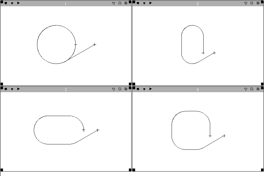
If necessary, the strategy is nominated on the GRADIENT SATISFACTION STRATEGY form. Note that only those strategies appropriate to the situation will be available for selection. Note also that if the spiral strategy only can be applied then there will be no prompt.
The screen is updated to show the generated path and its length is written to the message window. If the path can not be generated (if, for example, a maximum gradient of 0 was specified for a path between two points which have a vertical separation) then a warning message to that effect is written.