


Lighting options
This function allows you to artificially illuminate the data displayed on the screen. Surface rendering and shading will be applied to triobjects (DTMs) which have been drawn and strings which have been drawn as polygons. This adds another level of complexity to the viewing system and can add some time to the process of re-displaying a new view but the result achieved is generally worth it.
To run this function: Choose View > Surface view options > Lighting options, or...
Spot Light
The camera relative spot light that is inserted into the scene always shines from the camera location (your eye point) towards the target (the viewing point) regardless of how the scene is rotated or scaled. This provides consistent illumination without the dimming effect created by the lights provided by Directional Lights which always shine from the same absolute direction.
The colour of the camera relative spot light and the illumination cone can be controlled to achieve specific lighting effects.
Use spot light for dtm illumination
Check this box if you wish to have a camera relative spot light illuminating objects in your current viewport.
Illumination cone (degrees)
The width of the illumination cone can be defined as a number of degrees of arc. The illumination cone may be any value greater than 0 and less than 180. A cone of 180 degrees of arc will illuminate everything in front of the camera. Small values for the illumination cone will provide a tightly focussed light that only shines on a portion of the scene.
Sharpness cone (degrees)
The sharpness cone defines a ring inside the illumination cone inside which the light is at full intensity. Note that the value for the sharpness cone must be equal to or less than that of the illumination cone.
The light intensity reduces linearly between the extent of the sharpness cone (at full intensity) to the extent of the illumination cone where it is at zero intensity.
Offset angle from camera->target (degrees)
The spot light is a camera relative light that shines directly from the camera position towards the target position. On surfaces that are predominately flat this can cause excessive glare when in plan view. This offset angle causes the camera to be offset from the camera position by an amount that is dependent upon the distance between the camera and target positions. The effect will be the same regardless of the scale of the data.
Spot light colour
Define the colour for the light source. Colour names may be simple names, for example 'red', 'green', 'blue' or complex names, for example 'light green', 'dark red', 'greenish blue'.
Often a small offset angle will give superior results by reducing the glare.
Directional Lights
Use directional light(s) for dtm illumination
Check this box if you wish to have directional lights illuminating objects in your current viewport.
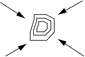
Up to three light sources may be inserted into the view, each of which illuminates with a specified colour from a specified direction. The source distance is considered to be at infinity so that the light rays are parallel. The position of the lights is defined as a vector rather than an absolute position. For example the vector of Y=0, X=0, and Z=1 defines illumination from directly above the data.
Y
Define the Y component of the vector to the light source.
X
Define the X component of the vector to the light source.
Z
Define the Z component of the vector to the light source.
Colour
Define the colour for the light source. Colour names may be simple names, for example 'red', 'green', 'blue' or complex names, for example 'light green', 'dark red', 'greenish blue'.
Rendering
Rendering method
Valid entries are:
- None. No lighting interpolation. The colour of a triangle face is fixed for the entire triangle face.
- Gouraud shading. This is a technique which is used to vary the colour across the triangle faces. This is done by determining the colour at each vertex and then interpolating this colour across the triangle.
- Phong shading. This is a technique similar to Gouraud shading which is used to vary the colour across the triangle faces. It generally more realistic results at the expense of increased processing time.
Both Gouraud and Phong shading tend to smooth the rough edges from objects and give a far superior graphic presentation of the data. Often Gouraud shading is implemented in hardware thus making it even faster than Phong.
Edge lighting
Check this box if you want lighting to apply to edges as well as faces. Leave the box unchecked if you only want faces to be shaded as lit.
Brightness factor
To prevent a washed out view when multiple lights are added to the viewport, the rendering method maintains the total brightness of lights added to a scene at a constant level. Unfortunately, this means that sometimes adding lights to a scene actually makes the scene appear darker.
To make the lights brighter if the view is too dark, select a larger value for this field; to make the lights dimmer if the view is too bright or "washed out", select a smaller value for this field.
Result
If the picture contains polygons or triobjects (DTMs) and the face attribute is on then the view will alter to show the surface shading effects of the defined illumination sources.
The diagram below shows an example of light source directions defined by vectors, where the light source is from above the surface as indicated by Z=1.
|
Y = 1 |
Y = 1 X = 1 Z = 1 |
|
|
||
| Y = -1 X = -1 Z = 1 |
Y = -1 X = 1 Z = 1 |