


Grade line setout notes
This function allows you to create setout notes to simplify setting out grade lines for underground mining. Grade line setouts are used to mark the nominal design level and gradient for the development of new underground workings. The information produced by this function is sufficient to enable the marking of the grade lines from selected stations in the underground workings.
To run this function: Choose Inquire > Grade line setout notes, or...
Before you use this function you must have the string for which setout notes are required recalled into the GRAPHICS module. This string will typically be the designed centre line string of the new development. It is imperative that this string have the correct design elevations of the new development.
You may also wish to use the Draw Survey Stations function to permit selected stations from your survey database to be displayed so that you can use existing stations as reference points for the setout notes.
Define the note file for setout data
The setout details will be written to a report file. You must enter the Location, Id number and Extension to define the file which will be created. The Description value which is entered is written to the report file to permit you to describe the setout notes which you are about to create. The Report writer is used to determine the format of the report file that is created.
Enter the offset from the design level to setout level
Offset
The elevations on the design are typically at the designed floor level or at the designed back level of the development. These are generally impractical levels at which to set out the features. Typically the grade lines are set out at a nominal eye height above the floor of the development, generally about 1.5 metres.
The Offset value which is entered here is applied to the elevations of the selected string before calculating the vertical offsets to the string.
Complete the Grade Line Setout Notes form to display the prompt:
Select backsight point
Position the cursor and select the point which is to be used as the backsight point.
Note:Any point at all may be used but you will find that it is most useful if you select a point which is a survey station which has been drawn from a survey database.
At the prompt:
Select setup point
Position the cursor and select the point which is to be used as the setup point.
Note:Any point at all may be used but you will find that it is most useful if you select a point which is a survey station which has been drawn from a survey database.
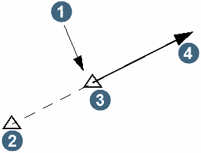
These two points define a base line from which the setout notes are referenced. The setup point is assumed to have a chainage of 0.0 and the positive chainage direction is measured away from the backsight station. The station elevations from the database which are used are determined when you use the Open Survey Database function.
|
1. change = 0.0 2. backsight 3. setup 4. positive change |
At the prompt:
Select the first point for grade line setout
Position the cursor and select a point on the string from which the setout notes are to commence.
At the prompt:
Select the second point for grade line setout
Position the cursor and select a point on the string at which the setout notes are to finish. Setout notes are generated for each discrete line segment (pairs of points) between the two points which are selected.
A file containing the setout notes similar to the following example is created. A description of the setout notes which are created by this function and an explanation of how to interpret the notes follows.
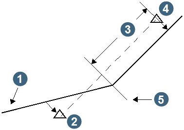
The notes include details of the backsight and setup stations, their coordinates and the bearing and distance between them. The setout data to the selected portion of the centre line string includes various items which are explained below. The notes give sufficient details from each of the stations to allow you to mark on a line hanging down from the station (plumb line) the gradient of each of the centre line string segments where a change of grade occurs.
Note:The chainages are distances measured from the setup station in a direction away from the backsight station. Offsets are measured from the line between the two stations.
|
1. centre line string 2. backsight station 3. relative chainage to 'change of grade' point 4. setup station 5. change of grade occurs here |
| Grade Line Setout Notes | |||||||||||||||||||||||||||||||||||||||
| Purpose: grade line setout notes | |||||||||||||||||||||||||||||||||||||||
| Station | Y | X | Z | Bearing | Distance |
| B | 100.000 | 200.000 | 100.000 | ||
| UG1 | 2.211 | 148.918 | 80.908 | 207.3452 | 110.327 |
| Station | Gradient (%) | Change
OF Grade distance |
Grade
Line z |
Vert. Offset | Horiz. Offset |
| B | -85.698 | -185.698 | -20.575 | ||
| UG1 | -239.720 | -341.674 | -422.582 | 7.171 | |
| B | -205.022 | -305.022 | -7.618 | ||
| UG1 | 75.964 | -69.659 | -121.448 | -202.356 | -15.874 |
| B | -274.246 | -374.246 | -5.982 | ||
| UG1 | 175.802 | -42.037 | -81.231 | -162.139 | -16.839 |
| B | -236.699 | -336.699 | 7.697 | ||
| UG1 | 143.346 | 3.762 | -82.265 | -163.173 | -16.076 |
Gradient %
The gradient of the section of the centre line string expressed as a percentage.
Change Of Grade Distance
This is the distance measured from the setup station to a point where a change in gradient of the centre line string occurs. There may be no notes in this column but if there are it is imperative that you pay special attention to them as it indicates a change in gradient in the centre line. Negative chainages indicate a distance from the setup station towards the backsight station.
Grade Line Z
The elevation of the grade line at the setup and backsight stations. It is used to determine the offset necessary from the station to the grade line. It takes into account the offset from the design level previously entered.
Vert Offset
The vertical offset from the backsight and setup stations to the grade line elevations. A negative values indicates a measurement down from the station and a positive value indicates a measurement up from the station.
Horiz Offset
The perpendicular offset distance from each of the stations to the selected centre line string. Typically the stations are aligned closely with the centre line of a drive but where they are not, the horizontal offset is useful for obtaining the correct alignment.
The Backsight and Setup points selected are the same.
			This is not permitted.
			Please reselect the points.
The points which you selected as backsight and setup points have the same Y, X, and Z values. This is not permitted. Try selecting the Backsight and Setup points again.
The First and Second points selected are not on the same segment. Please try again.
The points which you select for setting out must be on the same string segment. You must reselect both points.