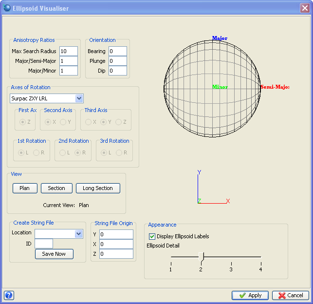
| Form Feature |
Description |
| The Display Area |
Both the ellipsoid and the axis can be fully rotated by holding down the
left mouse button whilst moving the mouse over the models.
|
| Ellipsoid |
A three dimensional wire frame model is used to represent the ellipsoid
and this is dynamically updated as you change the values in the various
input fields. The major, semi-major and minor axis are labelled and coloured
in order to distinguish them. |
| Axis |
The x, y and z axis are also labelled and coloured. The orientation of the axis when the ellipsoid visualiser is first invoked is always plan
view. |
| The Input Area |
The ellipsoid in the display area is updated when
focus is lost from an input field. Focus is lost by tabbing out of a field
or by clicking in another part of the form. If the input you provide is
valid for that field, then the ellipsoid model will reflect this information.
Invalid entries will be replaced by the last valid entry. |
| Anisotropy Ratios |
When you enter an anisotropy ratio, the ellipsoid changes shape. The
axes of the ellipsoid change length, hence changing the shape of the model.
|
| Max Search Radius |
You can enter a maximum search radius, for example 10. However this does not
have any effect on the three dimensional model. Instead, this will be
used in generating the string file. |
| Major/Semi-Major
|
This ratio must be greater than or equal to 1 AND less than
the major/minor anisotropy ratio. |
| Major/Minor
|
This ratio must be greater than or equal to 1 AND greater than the major/semi-major
ratio. |
| Orientation |
A ellipsoid can be defined by ZXY/ZYX (mathematical rotations) or by
ZXZ/ZYZ (geological rotations). The choice of axes affects the order of
data entry on the form.
ZXY and ZYX Rotations
The axis name for each order of rotations is as follows:
- 1st Axis (order of rotation) = Bearing (Axis name)
- 2nd Axis = Plunge
- 3rd Axis = Dip
ZXZ and ZYZ Rotations
The axis name for each order of rotations is as follows:
- 1st Axis (order of rotation) = Bearing (Axis name)
- 2nd Axis = Dip
- 3rd Axis = Pitch
|
| Bearing
|
This is the azimuth of the major axis in the XY plane and is rotated about
the minor axis.
The bearing must be between 0.0o and 360.0o inclusive
in order to be valid.
Entering a value of 45o in the bearing text box will cause the
ellipsoid to rotate 45o around the Z axis.
|
| Pitch/Plunge |
Valid axes are either X, Y or Z axis and is the semi-major axis. Valid
entries are -90 to 90. If the rotation is about the Z axis then it is
termed a pitch, if the rotation is about the X or Y axes it is termed
a plunge.
Plunge (ZXY) is the rotation around the X axis by the Y (plunge) value.
Plunge (ZYX) is the rotation around the Y axis by the X (plunge) value.
Pitch (ZXZ or ZYZ) is the rotation around the 2nd Z value after the dip
plane has been defined.
Adding the two Z bearings together will give a incorrect value e.g.
for a rotation convention of ZXZ, Z=30/X=40/Z=30 is not the same as Z=60/X=40/Z=0.
Inclination of a line: (a) plunge is measured in the vertical plane containing the
line; (b) pitch is measured in the inclined plane containing the line
(Structural Geology, 3rd Edition, Donald M Ragan, 1985).
|
| Dip |
Dip (or tilt) is the vertical angle between a line and the horizontal and
at right angles to the strike and can be positive or negative. If the
rotation convention is ZXY or ZXZ, the dip is the line measured from the
horizontal to the X axis while for a ZYX or ZYZ rotation convention, the
dip is the line measured from the horizontal to the Y axis.
The dip can also be used to define a geological dip plane using a rotation
convention of ZYZ (rotation around the Y axis) for a north/south striking
plane or ZXZ for an east/west striking plane (rotation around the X axis).
The final rotation using these conventions is a pitch defined by a rotation
around the transformed minor z axis which is now perpendicular to the
geological dipping plane.
ZXY is the rotation around the Y axis by the dip value.
ZYX is the rotation around the X axis by the dip value.
ZYZ is the rotation around the Y axis by the dip value.
A valid input is between -90.0o and 90.0o inclusive.
Valid axes of rotation are the X, Y or Z axis.
The dip is best viewed in section (looking along the major axis).
Entering a value in the dip text box will cause a rotation around whichever
axis (X, Y or Z) is selected in the third axis rotation panel.
Entering an invalid number in these text boxes will cause the text boxes to default back to the previous value. |
| Axes of Rotation |
Axes rotation can be divided into two parts, selecting the axis of rotation and selecting rotation direction around each axis. |
| Rotation around the axis
|
An easy way to visualise Z axis rotation is to place a map flat on a desk
and look down at it in plan view. Turn the map clockwise and you are rotating
the X and Y axes about the Z axis to the left (based on the left hand
rule below).
ZXY rotation.
Dip is the rotating around the Y axis (causes the X axis to dip).
Plunge is the rotation around the X axis.
ZYZ rotation.
Dip is the rotation around the Y axis.
Pitch the rotation within the dip plane, in this case the second rotation
around the z axis after the dip plane has been established.
If the pitch is 0o, then the structure is horizontal. If the
pitch is not 0o then the two Z values can not be added together
i.e. Z(20)Y(45)Z(60) is not equal to Z(80)Y(60)Z(0) or Z(0)Y(60)Z(80)
and Z(80)Y(60)Z(0) is not equal to Z(0)Y(60)Z(80).
The best way to visualise rotations is to get 3 toothpicks and colour
code them to the axis on the Ellipsoid Visualiser form (blue - major axis
(Y), red - semi-major axis (X) and green - minor (Z). Join the toothpicks
to form the 3 axis with the toothpick points indicating the positive direction
for each axis.
Enter values in the Ellipsoid Visualiser and compare the rotated toothpicks
with what is on the screen. |
| Rotation Direction |
Selecting the rotation direction is as important as selecting the axis
of rotation and can be compared to giving someone instruction to turn
without telling them to turn left or right.
Rotation direction has been defined using the left (L) or right (R)
hand rule.
The left hand rule is best visualised by holding an axis you wish to
rotate in your left hand with your thumb parallel to the axis and pointing
in the direction of increasing values. The fingers then curl around the
axis in the direction of a positive left hand rotation.
The right hand rule is similar except you use your right hand with the
thumb pointing towards the increasing values.
A left rotation is the same as a negative right rotation.
Notation used to describe the rotation convention is the rotation order
and then the rotation around each axis. For example ZXY LRL indicates
that the Z axis is a left rotation (first axis, first rotation), the X
axis is a right rotation (second axis, second rotation) and the Y axis
is a left rotation (third axis, third rotation).
Below is an example of what happens to the dip when the direction of
rotation is changed for Y axis (viewing in section).
The
rotations are ZXY LRR verses ZXY LRL (Surpac rotation convention).
A variety of rotation conventions can be selected from the drop down
box. Selecting "Other" in this box allows the user to create
their own convention by selecting the axis and rotation directions.
The rotation convention is recorded in any saved ellipsoid string files. |
| View |
By simply clicking one of the three view ports, the ellipsoid
and the axis will be positioned in the corresponding
plane.
Plan
The models will be aligned to look at the XY plane.
Section
The models will be aligned to look at the XZ plane.
Long Section
The models will be aligned to look at the YZ plane. |
| Appearance |
Toggle the displaying of the ellipsoid axis labels with the show labels
check box. Alter the level of detail of the ellipsoid using the slider. A value of
4 will smooth the surface of the ellipsoid, allowing the model to closely
resemble a solid, where as a value of 1 will give less detail to the model
and give the appearance of a squared surface. |
| Origin |
Use these input fields to specify an origin of your search ellipsoid. This
origin is used to create a string file. The default origin is 0,0,0. |
| Create string file |
Using the maximum search radius, the anisotropy ratios, the origin, and
the orientation, a string file of your ellipsoid can be generated. Specify
a file name and simply press the SAVE NOW button. You can create as many
ellipsoids as you like while the form is open. Change the details, change
the file name and press SAVE NOW. If you select the apply button on the
form and have not selected the SAVE NOW button, the string ellipsoid will
not be saved.
Having your ellipsoid saved as a string file opens all sorts of possibilities,
as immediately all the graphics functions become available. For example,
you could open the search ellipsoid string file with your block model,
or create a solid ellipsoid using SOLIDS - TRIANGULATE - MANY SEGMENTS
or SOLIDS - TRIANGULATE - CONNECTED SEGMENTS - ALL (after removing X,
Y and Z axis).
An audit trail is maintained when saving a string file. |



 Ellipsoid Visualiser form.