


Composite multiple elements
With this function you can calculate composite intervals based on a number of different compositing criteria. This can be important in the modelling of coal seams where the determination of the mining section must be based on a number of often conflicting quality criteria such as specific energy, sulphur content, ash content etc.
The resulting grades/qualities can be weighted by length alone or optionally by other fields in the table containing the sample data. This is useful if it is necessary to weight by specific gravity or recovery.
To run this function: Choose Database > Composite > Multiple elements, or...
Mining zones can be defined by using one or more grade compositing criteria for different fields and a logical expression to ultimately determine the mining interval. A single grade (or quality) compositing criteria has the following components:
- a field name from a single table in the database to define the grade or quality to be composited.
- the choice of either a minima or maxima constraint.
- a limiting value.
- missing sample treatment option.
- inferior sample treatment option.
Each compositing criteria will create a set of intervals down a drill hole independent of the other compositing criteria. These intervals must be combined to give a final set of intervals in which to calculate the composite values. A logical expression is used to combine the composite intervals to create a union (OR) or an intersection (AND) of the intervals.
Fields on the Multi element compositing form.
Define the output to produce
The results from multiple element compositing can either be output to a string file or a pre-existing database interval table.
Outputting to a string file
Select STRING FILE for the Output to field.
The location and ID number of the string file must be entered here, along with the string numbers to use for the output strings.
Valid composites will be output to the string specified by the String field.
The No zone string is used to output holes that do not intersect with the geological zones specified.
The No sample string contains all the drillholes that do pass through the geological zones but produce no composites.
Outputting to database table
Select DATABASE TABLE for the Output to field.
Enter the Database table to output the results to.
The choice of tables is limited to appropriate tables.
Valid output tables have the following properties:
- They are interval tables.
- The
samp_idfield allows null values (ie. is not a key field). - They contain a
widthfield which is of real type. - They contain a
weightingfield which is of real type.
Enter the log file to use. In the case that, for a given drillhole, output composites cannot be inserted into the database they will be written to this file.
Define the geological zones
Enter the method you wish to use for defining the samples to be selected for compositing as either:
NO SELECTION, do not select by geology, and so all samples in a drill hole will be used.MULTIPLE ZONES, define the interval by entering one or more geology codes.ZONE FROM TO, define the interval by entering the code at the top of the interval and the code at the bottom of the interval.
Multiple Zone Selection
If multiple geological zones are selected they may be intervening waste bands between them. Two further options, Waste interval treatment and Min waste width are used to determine how to handle these waste zones.
Waste interval treatment
INCLUDE WASTE, Samples in the intervening waste zones will be examined in the same way as samples in the surrounding ore zones.IGNORE WASTE, the waste intervals will be ignored completely in the determination of the composite.
Minimum waste width
A tolerance can be entered defining the minimum width of waste bands. This, in effect, splits the waste zones into two types:
- waste zones with width >= minimum waste width
- waste zones with width < minimum waste width
Compositing will NOT take place in waste zones where the width is greater than the
minimum waste width. In waste bands with width less than the tolerance
compositing will occur but only in a particular way; The samples in these
zones will NOT be used to check against the cutoffs for each criteria.
In this way they cannot degrade the quality of composites and hence the
choice of samples to include in a particular composite. However, the sample
information in these zones WILL be used to output the results to the string
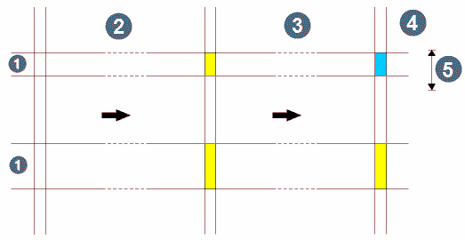
file or database table. Fig 1. below illustrates this option.
Note that the Waste interval treatment overrides the Minimum waste width option.
If the INCLUDE WASTE option is chosen there will be NO waste zones.
| GEOLOGICAL ZONE SELECTION | |
|
1. waste 2. drill hole before examining geological zone selection 3. drill hole before examining minimum waste width 4. drill hole after processing with respect to minimum waste width 5. minimum waste width |
| KEY | |
| Ore zones | |
| Waste zones with width >= minimum width | |
| Waste zones with width < minimum width | |
Sample table name
Enter the name of the database table containing the assay or quality data. The data must be stored in an interval table.
Maximum internal dilution
Material of less than the minimum value (when using a minima constraint) or greater than the maximum value (when using a maxima constraint) may be included in composites. The maximum permitted length of any internal low or high value material must be specified. If no internal dilution is to be allowed, enter zero.
Define output composite parameters
Composite reference point
When outputting to a string file the Y, X and Z coordinates of the
output data may be calculated as the point at the top, middle, or bottom
of the composite interval by choosing top, middle,
bottom. If segment is chosen, one segment per
composite interval will be created.
Minimum composite width
Enter the minimum width of the composites that will be generated. If a calculated composite is less than this length, it will rejected. Composites will only be generated for intervals equal to or greater than the minimum composite width. This value will be applied after the individual composite intervals have been merged using the composite combination.
Apply mining width
Enter YES or NO depending on whether mining
widths are to be applied or not. The default choice is NO
and will typically be the preferred option. Mining widths are usually
only considered as a final stage when examining the composites for a resource
and have the effect of producing at most one composite per drill hole
each with the same length as the mining width. This composite will either
be anchored to the top of the top-most composite or the bottom of the
bottom-most composite.
Normal operation without mining width
Select NO for the Apply mining width option.
Minimum composite spacing
Enter the minimum allowable gap between output composites in a
drillhole. Gaps that are smaller than this tolerance will be removed and
the surrounding composites will be merged together to form a single composite.
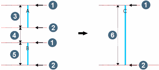
Fig 2. below illustrates this process.
Using a mining width
Select YES for the Apply mining width option.
Anchor position
Select the end of the drill hole to apply the mining width from - either TOP or BOTTOM.
Mining width
Enter the mining width to use.
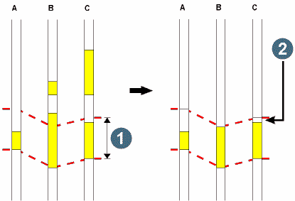
The following image illustrates the effect of mining widths.
| JOINING COMPOSITES | |
|
1. top of composite 2. bottom of composite 3. width of composite A 4. width is less than minimum composite spacing 5. width of composite B 6. width of composite C |
| top (C) = top (A) | |
| bottom (C) = bottom (B) | |
| width (C) = width (A) + width (B) | |
|
grade (C) = grade (A)*width (A) + grade (B) * width (B) |
|
| width (A)+width(B) | |
| MINING WIDTH | |
|
1. mining width 2. Note that waste material WILL be assessed in calculating final grades of composites |
Define optional weighting fields
If required, the calculation of the grades/qualities in the composite samples may be weighted by some other field/s in the sample table in addition to the length weighting already performed. Typically, additional weighting fields used would be specific gravity and/or recovery. A maximum of 5 additional weighting fields may be used. Enter the field name/s which are to be used to provide the additional weighting criteria for the creation of the composite intervals. Under some circumstances it is likely that no values may be available for the weighting field for some samples. The Default input field permits a reasonable default value to be defined to cover this circumstance. The default value is used in preference to the stored value in the table when either a NULL value is present or when the value present is less than zero.
Choose Apply to display the DEFINE THE COMPOSITING CRITERIA form.
Table name
The name of the table containing the assay or quality field data to composite is displayed.
Define the individual compositing criteria
One input line for each individual compositing criteria must be completed. Each line consists of:
- Tag.A letter is displayed to identify each compositing criteria and is called the composite tag. The tag is used to define the composite combination that determines how the individual composite criteria are used to determine the resultant interval.
- Field. The names of the optional field containing the numeric data that you want to composite.
- Operator. The operator that you wish to apply to the data in the nominated field. You can either select data greater than or equal to a particular value (>=), that is a minima constraint or less than or equal to a particular value (<=), that is a maxima constraint.
- Limiting value. Enter the limiting value to be used in the compositing criteria.
- Missing samples. Negative sample values are inferred as missing sample, and may be treated in the compositing process in one of three ways:
ZERO VALUE, the missing sample will be given a value of zero.INTERVAL MEAN, the missing samples will be ignored, and thus will have no effect on the composite value, and act as though they have a value equal to the mean of the interval.- User defined fixed value - enter in a real-type value.
- Inferior samples. Inferior samples are samples with values that do not satisfy the limiting value and operator constraint. They do NOT include missing samples.
USE VALUE, the value of the sample will be usedZERO VALUE, the inferior sample will be given a value of zero.INTERVAL MEAN, the inferior samples will be ignored, and thus will have no effect on the composite value, and act as though they have a value equal to the mean of the interval.- User defined fixed value - enter in a real-type value.
Note that the Missing samples and Inferior samples options are used only when comparing grades of composites against the Limiting value above and have no effect on the final grades produced for the output composites. Missing sample treatment for output composites is described below
Composite combination
Each line in the scrolling region describes a component of the compositing expression. These components are identified by the letter to the left of the line called the composite tag. For each line in the scrolling region for which you have supplied a composite expression, the tags must be combined in some logical expression to define the result of the compositing.
Enter a composite combination by using parentheses and the logical operators AND and OR to give something like:
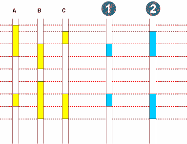
(a and b) or c The example below (Fig 4.) shows the composite intervals created using the above composite combination for some sample composites:
| COMPOSITE COMBINATION | |
|
1. A and B 2. (A AND B) OR C |
Output assay missing sample treatment
Enter the missing sample treatment. Negative sample values are inferred as missing sample, and may be treated in the compositing process in one of two ways:
VALUE, the missing samples will be given the values specified in the scrollblock described below.INTERVAL MEAN, the missing samples will be ignored, and thus will have no effect on the composite value, and act as though they have a value equal to the mean of the interval.
Define the sample fields required in the resulting string file
Field name
Enter the names of the sample fields containing the data that you want composited and reported in the string file. If you wish to composite the sample data from the fields that you are using to create the composite intervals, then you must also enter the field name here to have it reported, i.e. in the example above you would have to enter both `specific energy' and `sulphur' here to have them reported in the resultant string file/database table. Note that if the results are being inserted into a database table then only fields that exist in the output table can be chosen.
Missing sample value
Enter the value to use for missing samples.
Define code for composite intervals
Each drillhole interval produced by this function can be coded and output for later processing, interaction or reporting. The intervals can be saved to a database table for later work or graphics for immediate interaction with interactive compositing.
Write codes to
Select one of:
- database, to save the coded intervals to a database table.
- graphics, to save the coded intervals to graphics for interactive compositing.
- leave the field blank, to not save coded intervals.
Table name
Select the database table into which the current composite intervals will be written. We recommend that if you plan to save the composites to the database then you should create a separate table for storing the composite details. The reason for this is that the since these composites are the result of interpretation it is better to not mix them with actual measurements of the drill hole from the logging operation.
Certain actions are performed when saving the composite intervals to the database table to ensure that the integrity of data which may already exist in the table is maintained. The actions taken will depend upon how many existing samples for the drillhole exist within the depth_from and depth_to values for each composite interval. There are a number of different cases to be explained. Each of these cases are described in detail below:
- No existing samples overlap with the new composite interval.
In this case one new record is entered into the table with the depth_from and depth_to values of the composite interval and the composite code is saved to the nominated field. Any other fields in the table will have blanks or zeros stored for character and numeric fields respectively. Because of this you should ensure that the fields in the table will permit the entry of nulls. When the new samples are created, the only field which will have a value defined is the field to which the composite code is being saved.
- Existing samples overlap the new composite interval.
Any existing samples which overlap with the new composite intervals will be split so that the existing intervals no longer overlap with the new intervals. In addition a new record will be inserted if an overlap between the existing and new intervals exists at the top of the interval, and a new record will also be inserted if an overlap between the existing and new intervals exists at the bottom of the interval. These new intervals will have values saved to any optional fields to ensure that the integrity and contiguity of any existing intervals is maintained.
- Existing samples contained within the new composite interval.
Any existing samples which are completely included by a composite interval will have the composite code stored in the appropriate field and no further changes will be made to the existing sample.
Field name
Select the field in the table to which the composite codes will be written.
Interval code
The code to use for output intervals.
If you chose to select by geology, choosing Apply will display one of the two geological selection forms. See Geological Zone Definition.
Complete the zone selection forms and choose Apply to display the SELECT CONSTRAINTS FOR FIELDS form. See Selecting Data To Be Processed.
Complete the SELECT CONSTRAINTS FOR FIELDS form and choose Apply to commence processing.
Result (String File)
The output from this function will be a string file containing either a single point for each composite interval or a segment for each composite interval. The data saved in the various description fields is described in the table below.
| Field | Contents |
|---|---|
| D1 | Hole ID |
| D2 | composite width |
| D3 | Depth from |
| D4 | Depth to |
| D5 | Length weighted grade/quality of first composite field |
| D6 | Length weighted grade/quality of second composite field |
| Last Description field | This field only exists if optional weighting fields are used. This field will contain the total weighting value of all samples used in the composite. If weighting by specific gravity, dividing this value by the composite length will give the length weighted specific gravity. |