


Indicator kriging
This function produces the cumulative frequency function (cff) which is used in subsequent processing. This is a monotonically increasing function that maps cutoffs to kriged estimates of indicators based on those cutoffs. The monotonic nature of the function is ensured by correcting any order relation problems by replacing any disordered sequences with the mean of the values of that sequence.
To run this function: Choose Block model > Indicator kriging > Indicator kriging, or...
If a cff for the current attribute already exists a warning is displayed.
Note: An existing cff will not be replaced until all of the input for indicator kriging has been accepted and successfully processed.
Choose Apply to display the DATA SOURCE SPECIFICATIONS form.
Data source type
Enter where the data is to come from. This may be either a STRING FILE or a BLOCK MODEL.
Location, Id range, String range, D field
If the data source is a string file you must complete each of these inputs to describe the string file or files from which the sample data is to be obtained.
Enter the Location and Id range of the required string files. Enter the String range and the description field to define the data from the string file or files which are to be used for estimation.
Model name, Attribute
If the data source is BLOCK MODEL then you must enter the name of the block model and of the attribute within that model which is to be used as the data source for estimation.
Constrain data?
Enter 'Y' if you wish to restrict data selection or 'N' for unconstrained selection. See Make Constraint.
Constraining the data effectively removes all sample points which are not required completely from the estimation.
Special note:
Constraining the data source uses a block model constraint to determine which sample points to select. Consequently, if using a geometric constraint like inside a 3DM, above a DTM, etc., the sample points selected will not comply exactly with the geometric boundary. Rather they will be consistent with the block model constraint of the geometric boundary. This is an approximation which is dependent on the block model resolution.
If you checked the Constrain data? field the following field will appear:
Save constrained sample points?
Saving the constrained sample points to a string file can be used to confirm the correct constraint has been applied.
If you checked the Save constrained sample points? field the following two fields will appear:
Output location
Enter the location for the string file for saving the constrained points.
Output id number
Enter the ID for the string file for saving the constrained points.
Choose Apply to display the IK SEARCH AND ESTIMATION PARAMETERS form or Cancel to return to the INDICATOR KRIGING menu.
Search type
Enter the search type which may be ELLIPSOID or OCTANT.
A 3D ellipsoid search can be used if the data points used are reasonably distributed with no significant clustering. It simply uses the nearest samples to the block up to the maximum number specified.
An octant search should be used where there is significant clustering of the samples. It divides the horizontal plane into eight equal areas and takes up to n/8 samples from each octant for use in the estimation where 'n' is the specified maximum number of samples. If there are too many empty adjacent octants around a block then that block will not be estimated.
Use the Ellipsoid Visualiser to assist in defining your search ellipsoid.
Minimum number of samples to select
This sets a lower limit on the number of samples to use for a valid estimation.
Maximum number of samples to select
This sets an upper limit on the number of samples to use to minimise processing time.
Maximum search radius
The maximum search distance is used in conjunction with the maximum number of samples to select samples to be used in the kriging calculations. It should generally (although not necessarily) be set to a value slightly greater than the largest range of the indicator variograms for the major axis. The exception to this would be where it has been established that the kriging weights based on a typical block / sample configuration tend to zero at a distance shorter than this range. While the range of the variogram gives the maximum distance at which there is some correlation between data points, it is the magnitude of the kriging weights that ultimately determine the distance to which significant samples will be found.
The maximum search radius is measured in the direction of the major axis.
The search distances for the semi-major and minor axes are influenced by the anisotropy ratios which are used to define the shape of the ellipsoid. Only if these ratios are both equal to 1.0 will the maximum search distance be equal in all directions.
Maximum vertical search distance
This allows rejection of a data point if it is too far away vertically from the block to provide a meaningful estimation. Note that this is a VERTICAL search distance and is not influenced by the orientation of the search ellipsoid. To be used in estimating a value for a block, a point must first fall within the search ellipsoid and it must also be within the maximum vertical search distance.
Constrain by drill hole?
This option allows you to constrain sample points by selecting a limited number from each drill hole. This option will only appear if you defined your data to be from a string file (ie it won't appear if you have defined block model data).
If you checked the Constrain by drill hole? field the following two fields will appear:
Desc field
Enter the description field that contains the drill hole id. Hint: String file data is often produced from Surpac compositing functions. Each compositing function describes which description field the hole id is saved to, so the online documentation for the compositing function of interest should be reviewed for further details on where the hole id is stored.
Maximum number of samples per drill hole
Enter the maximum number of samples per hole that can be used in the estimation.
Maximum number of adjacent octants with no samples
This defines the maximum number of adjacent octants which may have no samples and yet calculations will still be performed (octant search only).
Number of descretisation points
These points will be distributed evenly through the block to allow the calculation of the extension variance for each sample.
Output filename
Enter the name of a '.not' file to which to write estimation parameters.
Include debug output
Enter 'Y' if you want an extended report or 'N' if you want only a summary of the estimation parameters.
Constrain interpolation?
Enter 'Y' if you wish to restrict the blocks to be estimated or 'N' for unconstrained interpolation. See Make Constraint.
Choose Apply to display the IK ANISOTROPY PARAMETERS form or Cancel to return to the DATA SOURCE SPECIFICATIONS form.
Each cutoff may have associated with it its own search anisotropy parameters that are used to determine distances of samples from the block centroid in order to select informing samples.
Cutoff
Enter the cutoff value from which indicators will be derived.
Bearing
This is the bearing of the major (long) axis of the anisotropy ellipsoid.
Plunge/Pitch
This is the angular displacement of the major axis from the horizontal in a vertical plane through the major axis.
The displacement is negative if the major axis plunges downwards.
Plunge is measured from a horizontal plane (measured from X or Y when rotation convention is ZXY or ZYX) and pitch is a measurement form an inclined plane (measured from Z axis if the rotation convention is ZXZ or ZYZ).
Dip
This is the angular displacement of the semi-major axis from the horizontal in a vertical plane normal to the major axis. The displacement is positive if the dip is to the left looking down the plunge of the major axis.
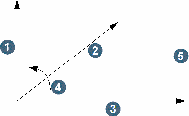
1. minor axis
2. major axis
3. semi-major axis
4. positive tilt direction
5. tilt about major axis
Semi ratio
This is the ratio of the length of the major axis to the length of the semi-major axis.
Minor ratio
This is the ratio of the length of the major axis to the length of the minor axis.
Choose Apply to display the IK VARIOGRAM PARAMETERS form for the first cutoff or Cancel to return to the IK SEARCH AND ESTIMATION PARAMETERS form.
Use these forms to enter the variogram parameters for each cutoff. Note the Next and Previous buttons used to navigate back and forth through the cutoffs and that the parameters for each cutoff default to those previous.
Variogram file name
Enter the file name containing the variogram model parameters to use. After a value is selected and focus is moved to another field on this form, the file will be read and the variogram model parameters will be populated into the variogram parameter fields. These fields can be modified if necessary before applying the form. Leave this field blank if the variogram model parameters to use have not been saved to a file.
Model Type
Select the model type (Spherical, Exponential, Gaussian, or Hole Effect) to be used for kriging.
Nugget
This is the nugget (Co) value for the model.
Sill, Range
Enter the sills (Cn) and ranges (a) for each structure in the variogram model.
Each structure in nested variogram parameters may be associated with different anisotropies. The defaults for these are provided by the search anisotropies specified for the cutoff.
Bearing
This is the bearing of the major (long) axis of the anisotropy ellipsoid.
Plunge
This is the angular displacement of the major axis from the horizontal in a vertical plane through the major axis. The displacement is negative if the major axis plunges downwards.
Dip
This is the angular displacement of the semi-major axis from the horizontal in a vertical plane normal to the major axis. The displacement is positive if the dip is to the left looking down the plunge of the major axis.
major/semi
This is the ratio of the length of the major axis to the length of the semi-major axis.
major/minor
This is the ratio of the length of the major axis to the length of the minor axis.
Choose Next or Previous to move between forms for different cutoffs. Choose Cancel at the first form to return to the IK ANISOTROPY PARAMETERS form or Apply at the last form to perform indicator kriging.
A number of real attributes (one per cutoff) representing the cff will be added to the model.
Messages
Must specify at least one cutoff
At least one cutoff must be specified in the IK ANISOTROPY PARAMETERS form for the from to be valid.
Read ??? for results.
Refer to the specified file for results of the indicator kriging.
??? blocks processed.
The given number of blocks were estimated.
No model loaded or attribute not selected.
Either there is no current model or there is no specified attribute with which to do indicator kriging. Use BLOCK MODELLING Graphics or MODEL Select Model to select a model, or use FILL Indicator Kriging to select an attribute.